机构名称:
¥ 1.0
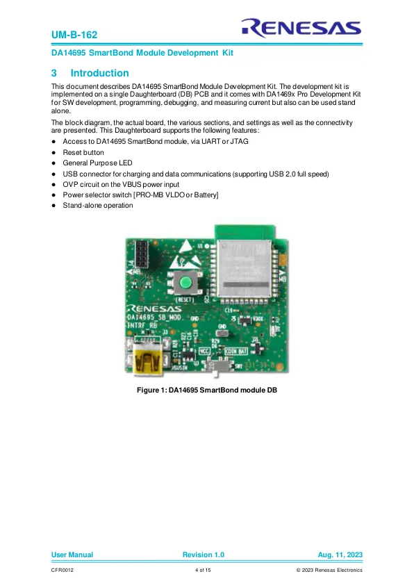
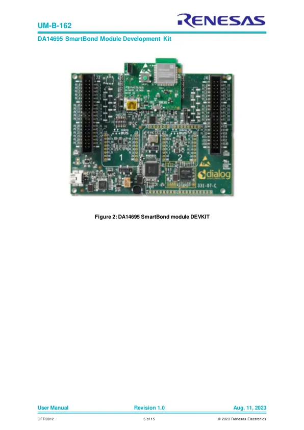
Figure 1: DA14695 SmartBond module DB...............................................................................4 Figure 2: DA14695 SmartBond module DEVKIT........................................................................5 Figure 3: Component description – top side ..............................................................................6 Figure 4: Component description – bottom侧面............................................................................................................................................................................................................................................................................................................................................................................................................................................................................................................................................................................................................... button on DA14695 SmartBond module DB........................................................9 Figure 9: General purpose LED on DA14695 SmartBond module DB ......................................... 10 Figure 10: CIB (JTAG/UART interface) connector (J4) ............................................................. 10 Figure 11: Schematic of DA14695 SmartBond module DB [331-39-B], Page 1 ............................. 11 Figure 12: Schematic of DA14695 SmartBond module DB [331-39-B], Page 2 ............................. 12 Figure 13: Components on top/bottom side for DA14695 SmartBond module DB [331-39-B].......... 13
UM-B-162:DA14695 SmartBond模块开发套件
主要关键词
相关文件推荐