图0-1,从alpha到达的围栏........................................................................................................................................................................................................................................................................................................................................................................................................................................................................................................................................................... 70-2, Packing Label Location..............................................................................................................................................7 Fig.1-1, PN-4 FT Enclosure.....................................................................................................................................................8 Fig.1-2, PN-4 FTB Enclosure...................................................................................................................................................8 Fig.2-1,PN-4 ft或PN-4 FTB外壳的单个宽混凝土垫..................................................................................................................................................................................................................................................................................................................................................................................................................... 102-2, Single-Wide Pad for PN-4 FT or PN-4 FTB Enclosures............................................................................................ 11 Fig.2-3, Double-Wide Pad for PN-4 FT and PN-4 FTB Enclosures........................................................................................12 Fig.2-4, Suggested Grounding..............................................................................................................................................14 Fig.3-1,PN-4 ft机柜安装在准备好的垫子上...........................................................................................................................................................................................................................................................................................................................................................................................................................................................................................................................................................3-2, FBX-60A on PN-4 FT Enclosure...............................................................................................................................17 Fig.3-3, BBX 70A (BBX-F12).................................................................................................................................................17 Fig.3-4, BBX 100A (BBX-F18)................................................................................................................................................17 Fig.3-5, MTS (Showing 100A and 60A boxes)......................................................................................................................17 Fig.3-6, BBX-100A-8P0S Service Disconnect.......................................................................................................................18 Fig.3-7, BBX-70A Service Disconnect...................................................................................................................................19 Fig.3-8, Schematic: Primary Service BBX-100A-8P0S with IPP-240-3..................................................................................20 Fig.3-9,示意图:带有IPP-1220-3的初级服务BBX-100A-8P0 ..3-10,示意图:带有IPP-120-2的二级服务BBX-100A-8P0 ..3-11,示意图:带有IPP-240-2的二级服务BBX-100A-8P0 ..3-12, Schematic: Secondary Service BBX-70A with IPP-120-1.......................................................................................22 Fig.3-13, Schematic: Primary Service BBX-70A with IPP-240-1...........................................................................................22 Fig.3-14, Connector Fitting in Rear of Equipment Tray..........................................................................................................23 Fig.3-15, Location of SPI in Equipment Tray..........................................................................................................................23 Fig.3-16, SPI Ground Wire Connected to Enclosure Ground Bar..........................................................................................23 Fig.3-17, Conduit Location.....................................................................................................................................................24 Fig.3-18, Coaxial Connectors................................................................................................................................................24 Fig.3-19, AlphaCell ® 210 FTX Battery Date Code..................................................................................................................25 Fig.3-20, In-Line Fuse Link Mounting...................................................................................................................................25 Fig.3-21, In-Line Fuse Cable.................................................................................................................................................25 Fig.3-22, BIU Tamper Switch Location..................................................................................................................................26 Fig.3-23, Conduit Pass Through............................................................................................................................................26 Fig.3-24,路由导管地下示例....................................................................................................................................................................................................................................................................................................................................................................................................................................................................................................... 27 3-25, Removing Battery Hardware..................................................................................................................................28 Fig. 3-26, Installing Battery Cables and Intercell Fuses.........................................................................................................28 Fig. 3-27, Trimming Battery Cover on PowerSafe ® SBS190F Batteries...................................................................................28 Fig. 3-28, XM3.1-HP Power Supply Smart Display.................................................................................................................29 Fig. 3-29, PN-4 FT XRT-TPPL Power System Wiring Diagram................................................................................................30 Fig. 3-30, PN-4 FTB XRT-TPPL Power System Wiring Diagram.............................................................................................31 Fig. 3-31, BIU Extension Connections to XM3.1-HP Power Supply.......................................................................................32 Fig. 5-1, Security Screw Dimensions....................................................................................................................................34 Fig.3-24,路由导管地下示例....................................................................................................................................................................................................................................................................................................................................................................................................................................................................................................... 273-25, Removing Battery Hardware..................................................................................................................................28 Fig.3-26, Installing Battery Cables and Intercell Fuses.........................................................................................................28 Fig.3-27, Trimming Battery Cover on PowerSafe ® SBS190F Batteries...................................................................................28 Fig.3-28, XM3.1-HP Power Supply Smart Display.................................................................................................................29 Fig.3-29, PN-4 FT XRT-TPPL Power System Wiring Diagram................................................................................................30 Fig.3-30, PN-4 FTB XRT-TPPL Power System Wiring Diagram.............................................................................................31 Fig.3-31, BIU Extension Connections to XM3.1-HP Power Supply.......................................................................................32 Fig.5-1, Security Screw Dimensions....................................................................................................................................34 Fig.5-2, Template Placement on Enclosure...........................................................................................................................34 Fig.5-3, Installing Brackets....................................................................................................................................................35 Fig.5-4, Installing Security Bar..............................................................................................................................................35 Fig.5-5, Battery Interface Unit Front.....................................................................................................................................36 Fig.5-6, BIU Mounting Ear (Horizontal Position)...................................................................................................................36 Fig.5-7, BIU Mounting Ear (Vertical Position).........................................................................................................................36 Fig.5-8, BIU Mounting Ear (Alternate Position).....................................................................................................................36 Fig.5-9, BIU Mounting Locations..........................................................................................................................................37 Fig.5-10, IPP for One Power Supply......................................................................................................................................37 Fig.5-11,一个电源(不是工厂预接)的Breaker Duplex选项(BDO)........................................................................................................................................................................................................................................................................................................................................................................................................................... 37FIG。5-12, LA-P+ Installed in BDO..........................................................................................................................................38 Fig.5-13, Location of LED on LA-P+.....................................................................................................................................38
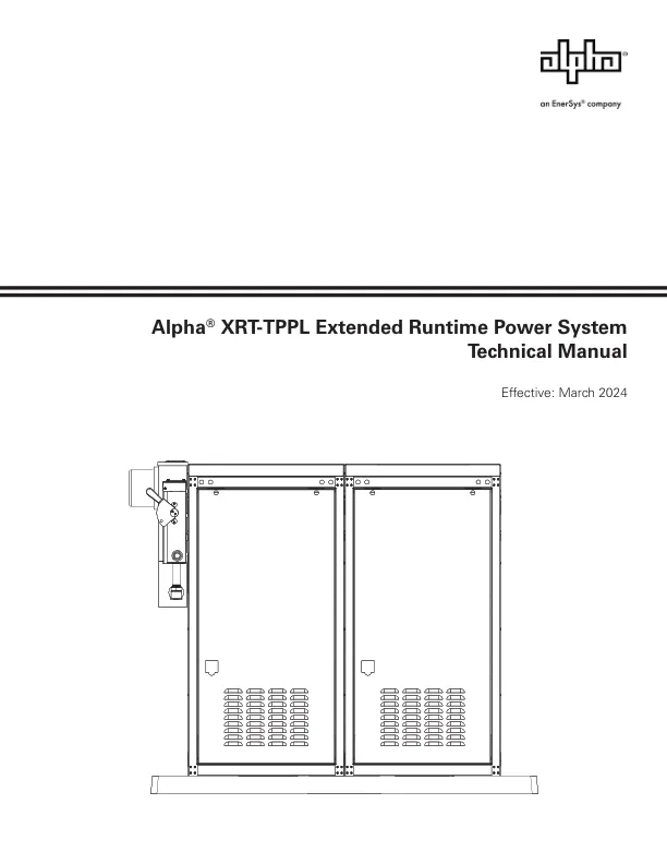
alpha®XRT-TPPL扩展运行时电源系统技术手册
主要关键词
