XiaoMi-AI文件搜索系统
World File Search SystemDIAGRAM
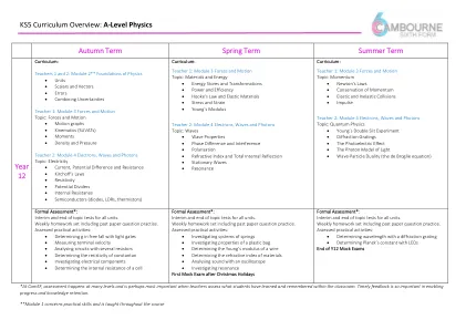
KS5课程概述:A级物理学秋季术语...
• Gravitational Fields • Kepler's Laws and Satellites • Life-Cycle of Stars and Hertzsprung-Russell Diagram • Absorption Spectra • Black Body Radiation • Wien's Law and Stefan's Law • Hubble's Law and the Big Bang Theory • Cosmology and Dark Matter Teacher 2: Module 6 Particles and Medical Physics Topic: Medical Imaging

ESS样本簇(更新)
(1)章节图中的海洋脊的海洋壳A现在是图表c中发现的最年轻的正常磁性岩石。(2)章节图中的海角A的海角A现在是图表c中发现的最古老的正常磁性岩石。(3)示意图中最接近海洋中部脊的反向磁性极性岩石比最接近章节图中的中端脊的反向磁极性岩石年轻。(4)构图图B中的反向磁性岩石与框图b中的正常磁极岩相同的年龄b。

2025条例
Ignoring BPS Fault Indicator .............................................................................................................. 60 Appendix A.Steering Wheel Specifications ................................................ 61 Appendix B. Occupant Space Diagram ........................................................ 62 Appendix C. Reference Standard for Lighting ............................................ 63 Appendix D. PVDR - Instructions ................................................................. 64 Appendix E. Mechanical PVDR Form ................................................................................................................................................................................................................................................................................................................................................................................................................................................................... 65附录G.机械VDR表格...........................................................Solar Cell Report ....................................................................... 72 Appendix J.建议.................................................................................................................................................................................................................................................................................................................................................................

消防安全研究史密斯菲尔德电池储能系统...
Figure 3.1: Site location and local surrounds .......................................................................................... 20 Figure 3.2: Neighbouring sites and offsite receptors ............................................................................... 21 Figure 3.3: Smithfield BESS layout ......................................................................................................... 22 Figure 4.1: Fire Safety Study flow diagram ............................................................................................. 24 Figure 5.1: Location of fire incidents carried forward for fire consequence review ................................. 30 Figure 7.1: SEF fire equipment................................................................................................................ 42
C-PCR-024 PV组件
4.1 Declared/functional unit ....................................................................................................................................................... 10 4.2 Technical specification, lifespan and reference service life (RSL) ........................................................................................ 10 4.3 System boundaries .............................................................................................................................................................. 10 4.4 System diagram ................................................................................................................................................................... 10 4.5 Cut-off rules ......................................................................................................................................................................... 11 4.6 Allocation rules .................................................................................................................................................................... 11 4.7 Data quality requirements .................................................................................................................................................... 11 4.8 Environmental performance indicators ................................................................................................................................. 13 4.9 Including multiple products in the same EPD ....................................................................................................................... 13
漂移角理论应用于船舶操纵模型。
船舶的六个自由度 ................................................ ..船舶轴线相对于 Eanh 轴线的相对位置 .................................. .涌浪力与涌浪速度之间的图形关系 阻力曲线的图形表示 ................................ .螺旋操纵的图形表示 ................................ ..舵角和角速度图的绘制:(A)动态稳定船舶 ............................................................. ..舵角和角速度图的绘制:(B)动态不稳定船舶 ............................................................. .. GZ 曲线的图形表示:(A)静态稳定船舶 ............................................................. .GZ 曲线的图形表示:(B)静态不稳定船舶 ................................................................ .. 推力曲线的图形表示 ................................................ ..动态稳定船舶的 Kemf Zig zag 机动 动态不稳定船舶的 Kemf Zig zag 机动 ............................................................................................................. .阻力曲线的图形说明 ............................................................................. .比例模型阻力曲线的图形表示 .. .. 纵向拖曳时舵处于攻角的模型方向 ............................................................................. ..显示测量的偏航力矩和舵角的图表 ............................................................................................. .显示测量的摇摆力和舵角的图表 ...... .比例模型阻力曲线图 ................................ ..攻角模型方位图:(A)舵与模型中心线对齐 ........................ .攻角模型方位图:(B)舵与拖曳水池中心线对齐 ........................ .. JL/测量比例模型图示:偏航力矩与摇摆速度图 ........................ .测量比例模型图示:摇摆力与摇摆速度图 ................................ ..平面运动机构图示 ................................ .船首和船尾之间相位差为零的模型轨迹 ............................................................................................. .PM M 下模型的正弦路径...................................... ..模型的旋转臂运动................................................ ..显示测量的摇摆力与角速度的关系的图表............................................................................................. .显示测量的偏航力矩与角速度的关系的图表............................................................................................. ..

AAG:用于评估机器学习模型针对对抗性
•系统上下文图:显示与系统相互作用的用户和外部实体。•容器图:这将系统表示为相互交互的一组独立服务。•组件图:将每个容器分解为详细信息到详细的组件,作为功能块执行特定任务的功能。•代码图:描述每个组件的实现,使用uml uml uml uml duagram andity duagram duagram andity duagram duagram andity duagram duagram andity duagurape andity die tie diagragram andity die diagumal diagumals andity diabes。

SMART Digital S - 格兰富
3.功能 7 功能概述。。。。。。。。。。。。。。。。。。。。。。。。。。。。。。。。。。。。。。。。。。。。。。。。。。。。。。。。。。。。。。。。。。。。。。。。。。。7 功能描述。。。。。。。。。。。。。。。。。。。。。。。。。。。。。。。。。。。。。。。。。。。。。。。。。。。。。。。。。。。。。。。。。。。。。。。。。。8 控制立方体 DDA 和 DDC。。。。。。。。。。。。。。。。。。。。。。。。。。。。。。。。。。。。。。。。。。。。。。。。。。。。。。。。。。。。。。。。。。。。。9 菜单。。。。。。。。。。。。。。。。。。。。。。。。。。。。。。。。。。。。。。。。。。。。。。。。。。。。。。。。。。。。。。。。。。。。。。。。。。。。。。。。。。。。。。10 种操作模式。。。。。。。。。。。。。。。。。。。。。。。。。。。。。。。。。。。。。。。。。。。。。。。。。。。。。。。。。。。。。。。。。。。。。。。。。。。。。11 个函数。。。。。。。。。。。。。。。。。。。。。。。。。。。。。。。。。。。。。。。。。。。。。。。。。。。。。。。。。。。。。。。。。。。。。。。。。。。。。。。。。。。13 接线图,DDA 。。。。。。。。。。。。。。。。。。。。。。。。。。。。。。。。。。。。。。。。。。。。。。。。。。。。。。。。。。。。。。。。。。。。。。。。。。19 接线图,DDC。。。。。。。。。。。。。。。。。。。。。。。。。。。。。。。。。。。。。。。。。。。。。。。。。。。。。。。。。。。。。。。。。。。。。。。。。。20 接线图,DDE-PR,-P 。。。。。。。。。。。。。。。。。。。。。。。。。。。。。。。。。。。。。。。。。。。。。。。。。。。。。。。。。。。。。。。。。。。。21

共同开发新南威尔士大学的社会影响框架
图 1*:此图说明了社会影响框架与新战略的对应关系。核心活动和支持功能反映了当前的优先事项,并可能随着新战略的发展而发展。 *请注意,此图仅供参考,并非最终版本,将随着社会影响框架研究的进展而更新。