XiaoMi-AI文件搜索系统
World File Search Systemfigure

经济部(原籍证书)
Figure 1: Login Screen ................................................................................................................................... 5 Figure 2: Sign in with UAE Pass ..................................................................................................................... 6 Figure 3: Login by UAE Pass .......................................................................................................................... 6 Figure 4: Dashboard - Screen ........................................................................................................................ 7 Figure 5: Tasks - Screen ................................................................................................................................. 8 Figure 6: In-Progress请求 - 屏幕....................................................................................................................................................... .................................................................................................................................................................................................................................................................................................................................................................................................................................................................................................................................................................................................................................................................................................................................................................................................................................................................................................................................................................................................................................................................................. 14:制作人资格 - 提交请求屏幕............................................................................................................................................................................................................................................................................................................................................................................................................................................................................................................................................................................. ...............................................................................................................................................................................................................................................................................................................................................................................................................................................................生产者公司 - 屏幕。
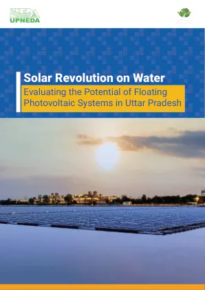
水上的太阳革命
List of Figures Figure 1: Schematic of an FPV system 8 Figure 2: Schematic of a Floating Platform 9 Figure 3: Schematic of an Anchoring and Mooring System 10 Figure 4: UP Solar Energy Target 13 Figure 5: Year-on-Year solar installed capacity in UP 14 Figure 6: Approvals necessary to set up an FPV project 17 Figure 7: GIS image representations for water boundary extraction in Lalitpur and Sonbhadra districts 20 Figure 8: GIS image representations for depth estimation in Lalitpur and Sonbhadra districts 21 Figure 9: District-wise distribution of water bodies in UP 22 Figure 10: FPV potential varying by water body coverage 23 Figure 11: District-wise FPV deployment potential (in MW) by varying percentages of water body coverage (20%, 25% and 30%, clockwise) 24 Figure 12: GIS image representations for proximity analysis to road networks in Lalitpur and Sonbhadra districts 25 Figure 13: Number of water bodies connected to a road network (< 2.5 km distance) 25 Figure 14: GIS image representation of water bodies located in protected areas 26 Figure 15: FPV potential of water bodies inside protected areas 27 Figure 16: Annual expected energy generation of FPV systems by varying probability of realisation and water body coverage 29 Figure 17: Monthly generation of FPV system varying by tilt angle and水体覆盖率29
添加剂制造的图像分析方法...
Figure 1- Flowchart of typical Additive manufacturing .............................................................. 1 Figure 2 – Schematic representation of the gas turbine [1]........................................................ 3 Figure 3 – Schematic explanation of the PBF process with Laser and Electron beam as the energy source [5]............................................................................................................................... 6 Figure 4 – Schematic explanation of DED [33]...............................................................................................................................................................................................................................................................................................................................................................................................粘合剂喷射[6] ................................................................................................................................................................... - 图像分析中的方法[11]。.................................................................................. 13 Figure 9 - Symbolic expression of Image processing................................................................ 14 Figure 10 - Flowchart of the Automated Image Analysis [11] ................................................. 18 Figure 11 - MIPAR software ......................................................................................................... 20 Figure 12 – Image J software ........................................................................................................ 22 Figure 13 – Grain size measurement objective .......................................................................... 23 Figure 14 – Defect Analysis Objective ........................................................................................ 23 Figure 15 – Manual measurement of defect Analysis ................................................................ 25 Figure 16 – MIPAR recipe ……................................................................................................................................................................................................................................................................................................................................................................................................................................................................................................................................................................................................................... Defect Analysis measurement .................................................................................. 30 Figure 21 – Porosity defect analysis plot ..................................................................................... 31 Figure 22 – Stitched image of the entire sample.
电池电动终端卡车课程汲取的报告...
List of Figures Figure 1: Patrick Terminals Fremantle ............................................................................................... 4 Figure 2: BEV- TT operations at Patrick Terminals Fremantle ............................................................ 5 Figure 3: PM115 (BEV-TT) undertaking 400A (~260kW) dual gun charging – image 1 ....................... 6 Figure 4: Charger setup including awnings......................................................................................... 6 Figure 5: PM115 (BEV-TT) undertaking 400A (~260kW) dual gun charging – image 2 ....................... 8 Figure 7: Typical 400A Charging Profile ............................................................................................. 9 Figure 3: BEV-TT delivering export containers to a quay crane ........................................................ 10 Figure 9: Typical BEV-TT Driving Profile .......................................................................................... 11
![[D1.6]传播和沟通计划...](/simg/d\d056db9495d40ed2eb28d5770d5327b0ebff31c1.webp)
[D1.6]传播和沟通计划...
图2-1:自动旋转项目的结构。_______________________________________________ 2 Figure 3-1: The two dedicated board of the AUTOFLEX Advisory Board ____________________ 5 Figure 4-1: The AUTOFLEX logo _________________________________________________________________ 6 Figure 4-2: Start page of the AUTOFLEX website ______________________________________________ 7 Figure 4-3: Journey of the AUTOFLEX project indicated by the project milestones ________ 8 Figure 4-4: Download section of the AUTOFLEX website _____________________________________ 9 Figure 4-5: Footer of the AUTOFLEX website __________________________________________________ 9 Figure 4-6: Users from different industries following the AUTOFLEX HEU Project _______ 10 Figure 4-7: AUTOFLEX at Zenodo ______________________________________________________________ 11 Figure 5-1: Start of the所有项目合作伙伴都可以使用______________ 13

可持续食品包装
图1:包装材料要求。.............................................................................. 9 Figure 2: PHAs Structure (Gomes Gradíssimo et al., 2020) .................................................... 12 Figure 3: PHBV structure (Boufarguine et al., 2013) .............................................................. 14 Figure 4:PLA structure (Boufarguine et al., 2013) .................................................................. 15 Figure 5:PBAT structure (Nobrega et al., 2012) ...................................................................... 19 Figure 6:Physical modification through blending will be used in our current project............. 23 Figure 7:Polymer blending ....................................................................................................... 24 Figure 8:Thermo Fisher Process 11 Extruder........................................................................... 25 Figure 9:Injection moulding ..................................................................................................... 25 Figure 10:conveyor belt section.41 Figure 24:TGA weight results 50%:50% blends ...................................................................... 41 Figure 25:TGA Derive weight, neat materials......................................................................... 42 Figure 26:TGA Derive weight 75%:25% blends..................................................................... 42............................................................................................................................................................................................................................................................................................................................................................................................................................................................................................................................................................................... ..................................................................................................................................................................................................................................................................................................................................................................................................................................... 75%的结晶度:25%混合物................................................................................................................................. ............................................................................... 34 Figure 17: Enthalpy cure for 75%:25% blends .................................................................................................................................................. 34 Figure 18: Enthalpy curve for 50%:50% blends ...................................................................... 34 Figure 19:FTIR neat materials ................................................................................................. 37 Figure 20:FTIR results, PHBV & PLA blends ........................................................................ 37 Figure 21:FTIR results, PHBV & PBAT blends ...................................................................... 38 Figure 22:TGA weight results, neat materials ......................................................................... 41 Figure 23: TGA weight results 75%:25% blends .
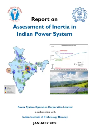
印度电力系统惯性评估的报告
Figure 1.1 Stages of power system frequency response after a disturbance ........................................................ 19 Figure 1.2 Frequency response during 12 March 2014 event ............................................................................... 20 Figure 1.3 Frequency response during 23 April 2018 event .................................................................................. 21 Figure 1.4 Frequency response during 28 May 2020 event ...............................................................................................................................................................................................................................................................................................................................................................................................................................................................................................................................................................................................................Frequency Drop .................................................................................................... 76 Figure 6.6 Power number during different grid events in India ............................................................................ 77 Figure 7.1 Flow chart for online inertia estimation ............................................................................................... 81 Figure 7.2 Online inertia monitoring in NRLDC EMS ............................................................................................. 82 Figure 7.3 Online inertia monitoring in WRLDC EMS ............................................................................................ 82 Figure 7.4 Online Kinetic energy monitoring in SRLDC EMS .................................................................................. 82 Figure 7.5 Online inertia monitoring in ERLDC EMS .............................................................................................. 82 Figure 7.6 Online inertia monitoring in NERLDC EMS ........................................................................................... 83 Figure 7.7 Online inertia monitoring for All India grid in NLDC EMS ..................................................................... 83 Figure 7.8 Sample daily kinetic energy curve for All Indian Grid ........................................................................... 84 Figure 7.9 Sample daily kinetic energy curve for NR ............................................................................................. 84
布雷姆纳社区1子 - 区域结构计划
图1。Location ........................................................................................................................ 55 Figure 2.Development Areas Concept ................................................................................ 56 Figure 3.Land Use Concept .................................................................................................... 57 Figure 4.Development Staging Concept ............................................................................ 58 Figure 5.Open Space Concept ............................................................................................... 59 Figure 6.Street Concept ........................................................................................................... 60 Figure 7.Transit Concept ......................................................................................................... 61 Figure 8.主动运输概念.........................................................................................................................................................................................................................................................................................................................................................................................................................................................................................行走........................................................................................................................................................................................................................................................................................................................................................................................................................................................................................................... 63图10。Stormwater Servicing Concept ......................................................................... 64 Figure 11.Wastewater Servicing Concept ......................................................................... 65 Figure 12.Waste Servicing Concept .................................................................................... 66
电池储能系统的可行性分析...
List of Figures Figure 1 Schematic diagram describing the design of a Lithium-Ion Battery [3] .................................... 5 Figure 2 Equivalent circuit for an electrochemical cell ........................................................................... 6 Figure 3 Typical Voltage behavior of the Li-Ion Battery.不同C率的不同曲线[6] ......... 7图4锂离子电池的电压作为不同C率的能量的函数[6]。............................ 9 Figure 5 Operation of a typical Li-ion battery [11] ................................................................................ 13 Figure 6 Typical cycle life of a Li-ion battery cell [11] ........................................................................... 13 Figure 7 Variability in demand and in net load in a challenging week on an area in USA.[31] ..................................................... 27 Figure 19 Maps of Chilean Photovoltaic Power Potential with the location of Campos del Sol [30] ... 27 Figure 20 Irradiation for different longitudes in a) Iquique and b) Copiapó's latitude.[35] ................ 28 Figure 21 Location of the project Campos del Sol PV Power Plant.来自Google Maps的照片。在每个跟踪器中都有28个模块。.................................................... 35 Figure 28 Shading analysis of the PV modules and the trackers ........................................................... 35 Figure 29 Campos del Sol considered losses.............................................................................................................................................................................................................................................................................................................................................................................................................................................................................例如四个不同的日子产生的PV功率,例如。 来自CEN网站。............................................................................................................................................................................................................................................................................................................................................................................................................................................................................例如四个不同的日子产生的PV功率,例如。来自CEN网站。来自CEN网站。................... 15 Figure 8 Power output of a PV plant in Southern California for a partly cloudy day ............................ 15 Figure 9 Balancing Technologies ........................................................................................................... 17 Figure 10 Basic concept of primary frequency regulation through ESS [23] ........................................ 19 Figure 11 : Frequency Control Methods and Relevant Time Scales in US [24] ...................................................................................................................图12频率控制时间尺度(激活时间是德国的示例)[24] ........................................................................................................................................................................................................................................................................................................................................................................................................................................... ................................................................................................ 23 Figure 16 Forecast of monthly power generation for Ollagüe's microgrid [27] ................................... 24 Figure 17 Maps of Chilean Global Horizontal Irradiation with the location of Campos del Sol [30] .... 26 Figure 18 Typical geography of the northern regions of Chile...................................................... 42 Figure 35 Energy profile produced by the PV in 25 years, with linear reduction of the power............................................................... 57 Figure 40 Variation of the relative initial cost of the BESS according to the size considered................................................... 60 Figure 44 Carrera Pinto 2020 Energy Price............ 30 Figure 22 Panoramic view of the area where the PV Plant will be situated (Google Maps) ................ 31 Figure 23 Carrera Pinto Interconnection Substation ............................................................................ 31 Figure 24 Irradiance of the area of Campos del Sol PV Plant ................................................................ 32 Figure 25 Module data .......................................................................................................................... 33 Figure 26 Inverter Data ......................................................................................................................... 34 Figure 27 Tracker structure......................................................................................... 36 Figure 30 Campos del Sol computed annual PV Power ........................................................................ 37 Figure 31 Campos del Sol generated Power for the first week of the year, computed with SAM ....... 38 Figure 32 Block Diagram of the Considered System ............................................................................. 40 Figure 33 Simplified Electric考虑系统的互连方案。................................ 43图36模型的温度评估模型................................................................................................................................. 57 Figure 41 Carrera Pinto Substation Energy Prices for different days of year 2020............................... 58 Figure 42 Considered Price Scenario ..................................................................................................... 59 Figure 43 Prices Profile Scenarios for the first three days of January........................................................... 65 Figure 45 NPV and Cash Flow for the BESS 50 MW 50 MWh................................................................ 66
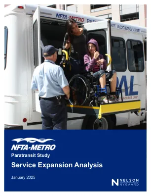
服务扩展分析-NFTA Metro | paratransit研究
Page Figure 1 PAL Study External Stakeholder Committee Members ................................................ 2 Figure 2 PAL Weekday Service (Midday and Peak) ........................................................................ 7 Figure 3 PAL Weekday Evening Service ............................................................................................. 8 Figure 4 Desired Travel Locations Identified During Engagement ......................................... 10 Figure 5 Inflation Factors Applied to Existing and Expanded PAL Service Costs ................ 12 Figure 6 Expansion to 3-mile Buffer ................................................................................................. 13 Figure 7 Expansion to 6-mile Buffer ................................................................................................. 14 Figure 8 Area, Population, and Annual PAL Trips Under Expansion Scenarios ................... 15 Figure 9 Annual Vehicle Hours and Vehicle Needs Under Expansion Scenarios ................ 15 Figure 10 Operating and Vehicle Costs in 2030 Under Expansion Scenarios ........................ 17 Figure 11 Items and Preliminary Costs for PAL Fleet Relocation and Expansion .................. 19 Figure 12 Summary of Service Expansion Operating and Capital Costs.................................. 20 Figure 13 Estimated Annual NDSP Operating Costs (2030) ........................................................ 21 Figure 14 Estimated Annual DSP Operating Costs (2030) ........................................................... 23 Figure 15 Recommended Consolidated Core Service Area ....................................................... 26 Figure 16 Recommended PAL Core Service and Express Corridor Spans ............................... 27